The experience of scanning devices application for quick inspection of
operated gas pipelines
Dr., Professor A.A. Dubov, M.Yu. Evdokimov, A.V. Pavlov
A number of outer flaw detecting scanners was developed and manufactured on
the instructions of GAZPROM JSC during the period of 2004-2006 for application
at diagnostics of gas pipelines in the course of re-isolation and other repair
works.
Multi-channel scanning devices (SD) for large-diameter (530÷1420 mm) pipes
inspection by the metal magnetic memory method supplied as a set with the
TSC-type instruments (Tester of Stress Concentration) were developed for the
same purpose.
At present Energodiagnostika Co. Ltd. manufactures three types of SD:
-
with full coverage of the entire pipe diameter and with the number of the
magnetic field measurement channels from 24 to 32;
-
with half-perimeter coverage of the pipe (up to 24 measurement
channels);
-
with partial pipe coverage on the perimeter length of 300-400 mm (12
measurement channels).
When these SDs are used, the inspection of the entire pipe surface can be
carried out at an average scanning speed of 10 m/min. At the same time isolation
removal and pipe surface dressing are not required. The method uses natural
magnetization of the metal formed in the course of operation (the magnetic
memory of metal). A flaw detecting scanner represents a device consisting of two
rings, being attached to each other, on which from 24 to 32 flux-gate sensors
are installed. These sensors are integrated with the wheels allowing the
operator to move the SD quickly along the pipeline. Papers [1, 2] present the
general view of the SD covering the entire pipe perimeter. SDs with partial
coverage of the pipe surface along its perimeter gained wide practical
application. The SC with 12 measurement channels of the magnetic field for
inspection of the most damaged pipe area, located near the longitudinal weld at
a distance of 200-300 mm to different sides of the weld, can serve as an example
of this.
The operator moves the scanner along the outer pipe surface using a distance
bar. The operator can be directly on the pipe or near the pipe (at a distance of
5-6 m), walking together with another operator, who watches the inspection
results on the screen of the specialized TSC-type instrument (Tester of Stress
Concentration, Certificate of the Russian Technical Regulation body
RU.C.34.003.A No.22257). The scanning device can be used as a set with a
laptop-based instrument.
The basic diagnostic parameter during the inspection of the outer surface of
pipes using the MMM method is the gradient dHp/dx of the magnetic field intensity (or
the intensity of its variation), which is recorded in the zones of developing
defects occurring due to stresses and strains concentration. While assessing the
state of the pipeline metal, it is necessary to know the limiting field
gradient, corresponding to the ultimate strength of the metal. These limiting
values are determined in the course of industrial and laboratory investigations.
From the positions of fracture mechanics, meeting the limiting state by the
metal does not depend on the type of defect causing this state. It is
characterized by the integral diagnostic parameter – the density of the
mechanical and, accordingly, the magnetic energy on the surface and in the
volume of the pipe body [3].
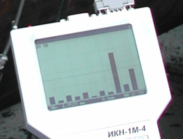
The magnetic field gradient, detected automatically in the course of
scanning, is displayed on the instrument screen as columns with binding to the
number of the sensor on the scanning device (see fig.1, a) as soon as
it crosses the defected zone.
When the limiting gradient of the field, set up beforehand at the instrument
adjustment, is exceeded on any of the measurement channels, the operator stops,
saves this zone in the instrument memory and tells another operator to make the
corresponding mark in the logbook or directly on the pipe surface (see fig.1, b).
 |
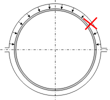 |
Fig.1a. Display of inspection
results on the screen of the instrument when the scanning device moves
along the pipe surface. |
Fig.1b. Marking of the
defected zone in the pipe logbook. |
The Methodical Guideline (MG) on carrying out the inspection of
large-diameter (?530÷1420mm) pipelines using the specialized scanning devices
were developed. This MG specifies the limiting field gradients for the above
mentioned diameters of pipes. These gradients characterize the limiting state of
the metal by the strength conditions, as well as the initial development of
cracks.
The existing experience in inspection using the metal magnetic memory method,
the TSC-type instruments and the scanning devices, which do not require any pipe
surface preparation, demonstrates the following: pipes, located on the same gas
pipeline segment and being in the long-time operation under identical
conditions, are in a distinctly different state. If in the course of the
inspection no magnetic anomalies are displayed on the screen, it indicates that
the pipe metal’s state is satisfactory and there are no developing defects on
it. At that the inspection speed is not higher than 2 min per 10 m of the pipe
length. In case the zones with the magnetic field gradient value higher than the
limiting values are detected, all these zones are marked in the pipe logbook
according to the described above technique. Then the qualifying inspection using
the eddy-current instruments and UFD is carried out in these zones.
It is appropriate to carry out the described above diagnostics of pipes using
the scanning devices in the field or factory conditions during the planned
replacement of insulation, on open above-ground pipeline segments, during
grading of used pipes, as well as before laying of new pipes into trenches.
In 2005 experts of Energodiagnostika Co. Ltd. carried out inspection in
winter route conditions of 1695 pipes (?1020ммx11mm), operated on the segment of
141-170 km of the Parabel-Kuzbass gas-main pipeline, and 1796 (?1020мм) pipes,
with thickness of 9,5 and 10,5 mm on the foundry-production section (FPS) in
Urga. In 2006 the same method way applied at various objects of Tomsktransgaz
Co. Ltd. for inspection of about 3000 pipes with the diameter of 1020 and 1220
mm. The pipes had been in operation for 20 years and longer.
The pipes, on which no unacceptable defects and stress concentration zones -
SCZs (the sources of damages) - were detected, were accepted as ready for
further operation. The wall thickness of these pipes was within the acceptable
limits.
The pipes with the limiting gradient of the magnetic field dH/dx in SCZs, containing various defects (pits on the
internal and external surface, lamination of the metal, mechanical damages,
etc.) and wall thinning in individual zones by more than 15÷20% were considered
as unsuitable for further operation.
As an example, fig.2 and 3 show the magnetograms, characterizing various
states of the metal of individual pipes. The magnetogram, shown in fig.2,
characterizes the unsatisfactory metal’s state of the pipe #46n. On this pipe in
the zone, where the values of the leakage field gradient dH/dx are higher than 15x103A/m2, the developing defects in the
form of corrosion pits were detected. Fig.3 shows the magnetogram,
characterizing the satisfactory metal’s state of the pipe #22n.
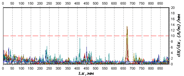
Fig.2. The inspection results of the pipe
#46n with pit-like defects at 141-170 km of the Parabel-Kuzbass GMP.
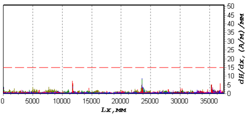
Fig.3. The inspection results of the
defect-free pipe #22n at 141-170 km of the Parabel-Kuzbass GMP.
It should be noted that on the above mentioned objects the inspection was
carried out with application of the described above scanning devices without
removal of the old insulation and without any pipe surface preparation.
In the course of inspection in route conditions 1131 (about 70%) of the
inspected 1695 pipes were accepted as ready for re-operation. The obtained
results of the quick inspection without insulation removal were further
confirmed by other NDT methods after the pipes were cleaned in the course of
their laying and re-insulation.
Application of SDs and instruments by the metal magnetic memory method
provides the opportunity to present the results of the quick inspection in the
pipe layout logbook. Fig.4 shows the distribution of stress concentration zones
(SCZs) with the field gradient value dHp/dx≥5.0x103A/m2. This pipe
layout was obtained based on the computer processing of the inspection results
using the "MMM-System" program after transferring to the PC of the data saved in
the TSC instrument memory. In fig.4 the isolines of the field gradient with the
field value of ≥5.0x10³A/m2 are outlined with thick lines,
corresponding to the boundaries of the defected zones.
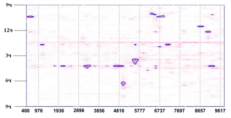
Fig.4. Distribution of SCZs with maximum
values of the Hp field gradient (dHp/dx) on the layout of
the pipe # 7321 (?1020x12mm).
In conclusion the following should be noted.
At present in the experimental-industrial operation of GAAZPROM JSC
enterprises there is already a diversity of flaw-detecting scanners by different
companies. These devices use magnetic (with artificial magnetization),
eddy-current and ultrasonic methods of inspection. However, to our opinion, at
scanners certification the commissions of GAAZPROM JSC pay insufficient
attention to the most important question - classification of recorded
signals by types of defects and processing of inspection results with binding to
the pipe layout. Exactly the inspection results and their objectivity,
i.e. their correspondence to actual defects, should be the basic factor when the
effectiveness of various flaw-detecting scanners is compared. This is especially
important because till date no standard and classification of signals by the
defect type and size exist for any of the inspection types (magnetic,
eddy-current, and ultrasonic) for the base metal of gas pipelines!
Based on the great experience in gas- and oil pipelines diagnostics using the
metal magnetic memory method Energodiagnostika Co. Ltd. possesses such
classification of defects by the parameters of the measured magnetic field and
its gradient. Further they have to be normalized. While carrying out the
diagnostic works on gas- and oil pipelines during their re-insulation and
performing of other repair works with the purpose of their acceptance for
further operation during a long period, to our opinion, it is necessary, besides
the ordinary flaw detection, to carry out the inspection of the pipes’
stress-strain state (SSS) with detection of SCZs, being the potential sources of
damages.
It is also necessary to carry out the inspection of pipelines’ SSS Контроль
in connection with putting in operation of the corresponding Russian and
International standards. In 2005 based on the International standard ISO 9712
and the European normative documents the RSNDTTD introduced a new type of
inspection - "Stress Control" - for the base metal and welded joints. Besides, a
new national standard of Russia GOST R 52330-2005 "Non-destructive testing.
Stressed-strained state test on industrial objects and transport. General
requirements" was put in operation in 2005.
As it is known, the MMM method and the appropriate TSC-type inspection
instruments simultaneously perform two tasks:
Application of the MMM method provides the possibility to carry out the
assessment of the degree of the defect’s hazard and to answer the question: "Is
the defect developing or not?" Such an approach is of principal significance as
well at carrying out the engineering diagnostics for risks evaluation during
gas- and oil pipelines operation.
Bibliography
1. A.A. Dubov, A.M. Gneushev, I.I. Veliulin. Assessment of
gas- and oil pipelines’ residual life based on modern methods of engineering
diagnostics // Gazovaya Promyshlennost. 2005. No.2. pp.76-78.
2. A.A. Dubov, V.A. Markelov, V.D. Kotov, Yu.I. Usenko.
Inspection and assessment of long gas pipeline segments’ lifetime // Gazovaya
Promyshlennost. 2006. No.8. pp.46-48.
3. V.T. Vlasov, A.A. Dubov. Physical Bases of the Metal
Magnetic Memory Method. Moscow: ZAO "TISSO", 2004. 424 p. |