Diagnostics of bends of boiler and steam tubes
One of the difficult problems of power engineering is to ensure reliability
of bends of unheated tubes in boilers and steam lines. In spite of a lot of
researching and measures taken within the branch Electric Power Engineering in
order to increase reliability of bends - no desirable results have yet been
achieved and boiler bends are still dangerous joints. The technique of early
detection of bend damages with usage of effect of metal magnetic memory is
developed. The existing methods of non-destructive control (ultrasonic
inspection, magnetic particle inspection) which are widely used in power
engineering are intended for search and detection of already developed defects
and various cracks in the equipment metal which is not acceptable if we consider
the problem of equipment reliability from the point of personnel security.
Herewith it is known that the main source of bend damage is concentration of
mechanic stresses caused by working loads. As a rule the bends operating in
conditions of additional (not calculated) stresses are damaged.
From the theory of strength and destruction mechanism we know that most
unfavourable for damage development in structures is such combination of loads
at which metal is locally affected by main tensile stresses. Herewith cracks are
formed on the planes perpendicular to the main tensile stresses. The long-term
experience of research of magnetic fields on boiler and steam tubes has shown
presence of steady lines of change of the sign of normal component of magnetic
intensity Нр in zones of
development of metal damages. This diagnostic parameter (the line Нр=0) was put in the basis of
testing techniques of equipment. The interpretation of this diagnostic magnetic
parameter, as line of primary stresses arising on a tube surface under operation
of working loads, is given in special paper. Obviously, that the coincidence of Нр=0 lines with tension or neutral
zones of bend is most dangerous for its reliability.
As an example we will consider testing of one of steam-by-pass tubes in
turbine PT-60, station number 3 of Diagilevskaya thermal power station (bend
№10, steel 15Cr1MoF, ?273х32 mm).
Testing was effected by means of two-channel detector of instrument TSC-1М-4
along the extended side of the bend. Fig.1,a presents epure of Нр field distribution detected in
the two-channel mode. As seen from fig.1,a, stress concentration zone
(SC) is characterized by an abrupt increase of Нр field. It should be noted that scanning along
the extended bend zone was made with the datum distance between ferroprobe
sensors 20 mm. Herewith abrupt change of Нр field was recorded mainly in one measurement
channel. Then there was testing made along the bend perimeter in the
cross-section of the bend with the abrupt increase of Нр.
Fig.1,b shows distribution of Нр field recorded along the bend perimeter
(cross-section A-A). The distance between ferroprobe sensors was also 20mm. From
fig.1,b can be seen that in one of the channels there was a significant
change of value and sign of Нр, in
the other channel - change of Нр field is less significant in value and without sign change.
 |
 |
Fig.1a. Distribution of Нр field recorded in two-channel mode. |
Fig.1b. Distribution of Нр field recorded along the bend
perimeter. |
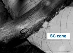
Fig.2,a shows stress concentration zone detected on bend №10 near
the extended side. SC zone is a spot in form of ellipsis of size 70x35 mm -
which is divisible by the wall thickness (32 mm). The spot is limited by line of
sign change of Нр field (line Нр=0). Fig.2,b shows a
fragment illustrating pinching of bend №10 (with SC zone) with the bleed-off
tube of the same turbine №3. It is obvious that it is the pinching of bend №10
at its temperature compensation that caused SC zone formation.
 |
|
Fig.2a. Stress concentration
zone detected on bend №10 near the extended side. |
Fig.2b. Fragment illustrating
pinching of bend №10 (with SC zone) with the bleed-off
tube. |
Fig.3 illustrates metal structure received from a replica taken from SC zone
(along the line Нр=0) on the bend
№10. As seen from fig.3 there were cracks detected in the metal structure on
this bend in SC zone - the distance between the cracks is approximately 0,1 mm.
Thus bend № 10 was in condition preceding damage.
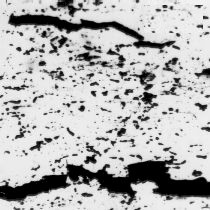
Fig.3. Metal structure received from a
replica taken from SC zone (along the line Нр=0) on the bend №10.
The given technique of bend inspection was agreed with Central Technical
Administrative Board of Department of Energy at 25 February 1991 and with State
Engineering Supervision (Gosgortechnadzor) of Russia at 26 February 1993, has
passed an industrial testing on a number of thermal power stations of Russia and
in other countries. The sizeable positive experience is accumulated. According
this experience the control of bends with usage MMM is effective in combination
with ultrasonic inspection and with the analysis of metal structure obtained
from samples with SC zones. This technique was added and revised in 2002. |