Diagnostics of pipelines, gas and oil pipelines
Fig.1 shows the general inspection scheme for all industrial pipelines using
the specialized magnetometric instrument �C the Tester of Stress Concentration
(TSC-type). The instrument has a screen, a memory unit for recording the
measurement results and a scanning device in the form of a trolley, on which the
sensors measuring the Hp magnetic
field and the pipelines length are installed. The inspection does not require
the preliminary preparation of the surface. In some cases the pipelines
inspection may be carried out without the insulation removal.
Fig.1. The scheme of a pipeline inspection
using a two-channel sensor: 1 - the scanning device with the length-measuring
sensor; 2, 3 - flux-gate transducers (the number of transducers may vary
from two to sixteen depending on the inspection tasks and the dimension-type of
the pipeline); 4 - the connecting cable; 5 - the TSC-type instrument with a
memory unit and a screen for displaying of the graphical information.
Fig.2 shows the fragment of the Hp magnetic field distribution along the segment
of the ?168��16 pipeline with a visible swag. The diagram of the Hp field distribution corresponds to the actual
strain of the gas pipeline.
Fig.2. The fragment of the Hp magnetic field distribution along the gas
pipeline segment: 1 - gas flow.
Ageing of oil- and gas-trunk pipelines places the task of their functioning
safety and reliability assurance in the list of the most important state
problems. At present the general length of trunk pipelines in Russia is over 300
thousand kilometers. And about 40% of gas pipelines and 60% of oil pipelines
have been in operation for more than 20 years.
It is obvious that the traditional approach to maintaining the pipelines
operability by performing overhauls of individual pipe segments mainly with
complete insulation coating and pipes replacement cannot provide safety and
reliability of gas-trunk pipelines because of their long length and distinctly
different state. Therefore operation and repair "according to the actual state",
i.e. shifting to selective "spot" repairs of elements and segments based on
results of the 100% diagnostic inspection of many-kilometers-long pipelines
becomes the main strategy for providing high reliability of trunk systems.
The following concept of long-term operated gas- and oil pipelines
reliability and safety assurance is suggested:
1. Analysis of damages, results of non-destructive and
destructive metal testing and of the carried out replacements of worn-out
segments based on the available statistics of an operating organization.
2. The 100% inspection of all gas and oil pipeline segments
using up-to-date NDT methods and means (in-pipe diagnostics, non-invasive
magnetometric diagnostics, the metal magnetic memory method, acoustic emission)
allowing carrying out the early diagnostics of damages and detecting stress
concentration zones (SCZ), which are the main sources of developing damages.
3. Additional inspection with traditional NDT means (USD,
X-ray, investigation of the metal��s metal mechanical properties and structure)
is performed on gas and oil pipeline sections with detected SCZs after the
"prospecting" operation.
4. For certain most stressed sections with SCZs left in
operation a confirmatory strength calculation is carried out taking into account
the pipelines�� metal damaging and wear nature.
5. The 100% fittings examination using the metal magnetic
memory method and other NDT methods.
6. Summarizing of the results of the complex 100% inspection
and developing of measures aimed at assuring gas and oil pipelines reliability
with making the replacement schedule of the physically worn-out pipe segments
being most susceptible to damaging.
The proposed concept is based on the assessment of the real gas and oil
pipelines�� lifetime since such an assessment most optimally combines the
operational experience (former damaging statistics) and the early diagnostics of
future damages using up-to-date methods.
Energodiagnostika Co. Ltd. developed a measuring complex (fig.3) for
non-invasive magnetometric inspection of gas and oil pipelines buried under the
soil layer of 2m and deeper. During the operator��s movement along the route at a
speed of not less than 2 km per hour the segments, operating in the most
stressed conditions and being susceptible to damaging, are detected. Prospecting
and additional inspection are carried out on these segments in order to detect
specific defects.
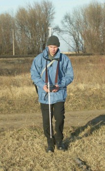
Fig.3. Non-invasive magnetometric inspection
of gas and oil pipelines buried under the soil layer.
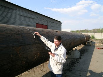
For on-line 100% inspection of welded joints and walls of large-diameter
(?530��1420mm) gas and oil pipelines a scanner-flaw detector was developed, which
allows carrying out the state assessment of the entire pipe surface at a speed
of 100 running meters per hour and faster (fig.4 and fig.5). Insulation removal
and the pipe surface dressing are not required, and the natural magnetization of
the metal, formed in the course of operation (the magnetic memory of metal), is
used.
 |
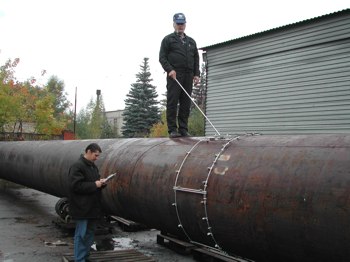 |
Fig.4. Inspection of gas and oil
pipelines by the contact method. |
Fig.5. Inspection of gas and oil
pipelines by the contact method. |
Fig.6 presents the inspection results of the strained gas pipeline segment
(?1420��18,7mm) at Urengoi GTP.
Fig.6. Results of the strained gas pipeline
segment inspection: 1 - SC zone.
The Methodical Guideline (MG) on non-invasive magnetometric diagnostics
(NIMD) of gas and oil pipelines using the TSC-type instruments is developed. The
proposed MG incorporates the description of the NIMD principle allowing
detecting and localizing stress-strain state and revealing the presence of
various-type damages in the metal of pipelines buried under the ground, water
and other media.
NIMD is based on measurement of the distortions of the magnetic field of the
earth (��earth) conditioned by changing of the pipe metal��s magnetic permeability
in SCZs and in the corrosion-fatigue damaging development zones. The ��earth
variation nature (frequency, amplitude) is conditioned by the pipeline strain
occurring in it due to the effect of a number of factors: residual process and
assembly stresses, working load and self-compensation stresses at the ambient
air and environment (soil, water, etc.) temperature fluctuations.
At decoding of magnetograms and classification of magnetic anomalies the
criteria developed based on the more than 20-years experience in the metal
magnetic memory method application at direct inspection of pipelines are
used.
The "MMM-System" software product is used for results processing and
detection of segments operating in the most stressed conditions.
Fig.7 and fig.8 show the fragments of the inspection results of individual
segments of gas and oil pipelines, buried under the soil layer at the depth of
two meters.
Fig.7 shows the results of a buried gas pipeline ?530, st.20) inspection. The
diagrams of the Hp field
distribution along the three components (normal and tangential (longitudinal and
transverse)) indicate the presence of the local variation of the magnetic field
with the maximum gradient in the SC zone (see the bottom part of the
magnetogram).
Fig.7. The results of a buried gas pipeline
segment inspection.
Fig.8 shows the distribution of the resulting Hp magnetic field over the oil pipeline ?219��8mm,
steel 20) buried under the soil layer at the depth of about 2 m. The marked SC
zones are characteristic of the pipelines operating in conditions of the lack of
self-compensation combined with high residual stresses after fabrication and
installation.
Fig.8. The distribution of the resulting Hp magnetic field over the oil
pipeline. |