Diagnostics of steam turbine blades
Inspection is carried out on the convex surface of the blade on the side of
steam inlet and outlet. Fig.1 shows the scheme of the blades inspection.
Scanning with the TSC-type instrument sensor is performed in the direction
from the blade root section to the peripheral section or conversely.
It is recommended to execute all the blades inspection operations
step-by-step for the blades of a specific stage.
In the course of the inspection the TSC-type instrument’s screen displays the
graphs of the Hp leakage field
distribution along the blade length. The inspection results are stored to the
instrument’s ROM for their further processing on the IBM-compatible
computer.
The blades operating in the most stressed conditions are determined based on
the inspection results. These are the blades with the stress and strain
concentration lines (SC lines) located transverse to the blade wing and having
the maximum Hp field gradient: Kin=dHp/dx. The value of the filed gradient Kin, characterizing the level of
residual stresses in the blade, is determined automatically and displayed on the
screen by the operator’s command. The technique for blades inspection, submitted
to the Customer, specifies the limiting values of the field gradient, which
precede the crack formation.
Fig.1. The scheme of turbine blades
inspection using the TSC-type instrument and the Type 2 scanning device: 1, 2 -
flux-gate transducers; 3 - length meter; 4 - connecting cable; 5 - TSC-type
instrument; 6 - blades.
Fig.2 shows the results of blades #31, 32 and 33 inspection of stage #33 of
the K-300-240 steam turbine low-pressure rotor (LPR) at Konakovo TPS using the
metal magnetic memory method. The distribution of the Hp field and, accordingly, of the field gradient
(dHp/dx)
recorded on the blade #31 (see fig.2, a) characterizes its satisfactory
state. It is seen in figures 2, b and 2, c that the abrupt
variation of the Hp field and,
accordingly, of the field gradient Kin was recorded on the blades #32 and #33 at
the distance of 180-200 mm from the root. Based on the available experience,
such Kin values are close to
limiting values. It should be noted that the numerical values of Kin also depend to some extent on the
sensitivity of the inspection instruments used.
Fig.2a. The distribution of the Hp field. Blade #31.
Fig.2b. The distribution of
the Hp field. Blade
#32.
Fig.2c. The distribution of the Hp field. Blade #33.
Fig.3 shows the lines of the field gradient Kin sign alternation, detected during the
more detailed measurement of the field on the surface of the blades #32 and #33.
As it was pointed out above, according to the technique, these lines correspond
to the SC lines, and exactly in these zones occurrence of the blades damaging
should be expected. The blades #32 and #33 were replaced, and the metallographic
investigation was carried out along the SC lines.
Fig.3. SC lines detected on the surface of
the blades #32 and #33: 1 - SC lines.
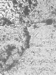
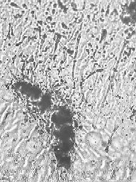
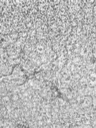
The pronounced corrosion-fatigue damaging of the metal, corresponding to the
pre-failure state of the blades #32 and #33, can be seen on the structure
fragments (magnification ×500) shown in fig.4,a and 4,b.
It should be noted that the maximum damaging of the metal's structure was
detected in the course of investigations exactly in the zones of the maximum Hp field gradient recorded during
the inspection near the SC line. The metal’s structure is satisfactory at a
distance of just 100 micrometers from the SC line (for example, see the
structure fragment shown in fig.4, c for the blade #33).
Of the total number of more than 800 LPR blades, inspected using the metal
magnetic memory method, only three blades in the pre-failure state were
detected. The non-failure operating time of these blades was ~ 200000 hours at
the date of inspection.
In the course of the industrial verification of the considered inspection
method Energodiagnostika Co. Ltd. accumulated the data bank of the numerical Kin values for the blades in the
pre-failure state for the last stages of the PT-60-130, K-100, K-200 and K-300
turbines. |