Inspection of wires and ropes
Inspection of wire
The presented below inspection technology can cover all types of
welding and spring wires.
To ensure installation, repairs and operation of parts installed in gas- and
oil-production boreholes the ?2,0 and ?2,6 steel wire is used. The wire is made
of steel 40-70 according to GOST 9389-75, GOST 1050-88, GOST 14959-79 and GOST
1435-90.
In the course of operation and repairs the wire damages occur, which causes
the large material loss. In order to prevent the occurrence of wire damages it
is necessary to develop and implement non-destructive testing methods, allowing
timely detection of stress concentration zones (SCZs). SCZs, being the sources
of damages development, may occur both on the new and used wire.
Based on the analysis of the results of experimental investigations, carried
out by Energodiagnostika Co. Ltd. experts on the ?2,0 and ?2,6 wire using the
metal magnetic memory method, the following conclusions were made:
-
The possibility to use the MMM method for quality inspection of both the
new and the used wire was revealed.
-
Inspection may be carried out at the production plant during the wire
rewinding from one spool to another and directly at the boring plant during
pulling-out or lowering-in of the wire.
-
The quantitative criteria of the metal’s limiting state of the various-type
wire were determined. These criteria need to be specified in the course of the
industrial implementation of the MMM method and the appropriate
instruments.
-
It was established that the MMM method and the instruments of the TSC-4M-16
type allow detecting SCZs and zones of developing damages on the wire surface
with the accuracy of up to 1 mm.
The main task of the MMM method consists in detection of SCZs, which are the
zones of the anomalous distribution of the magnetic leakage fields on the
surface of the inspected wire. Then, using the specialized "MMM-System" program,
the wire grading is carried out by the degree of its susceptibility to damaging
in SCZs. Screening and grading of the wire may be carried out directly during
the inspection by the values of Kin, corresponding to the wire metal’s
limiting state before the formation of cracks. The value of Kin, corresponding to the metal’s limiting
state, is determined in the course of experimental investigations separately for
each dimension-type of the wire.
The inspection of the wire may be carried out both in the steady-state (at
the plant) and in the field conditions near the boreholes.
In the steady-state mode the inspection is carried out during the wire
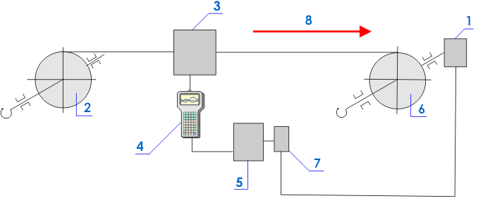
rewinding from one spool to another. Fig.1 shows the inspection scheme.

Fig.1. The scheme of the device for the wire
inspection: 1 - the drive motor; 2 - the driven spool; 3 - the specialized
sensor; 4 - the instrument; 5 - the operator’s place; 6 - the driving (winding)
spool; 7 - the control panel of the drive motor; 8 - the direction of the wire
rewinding.
The drive motor 1 rotates the winding spool 6 at a constant
specified rotating speed. The wire moves inside the guiding device combined with
the measuring sensor 3. During the motor rotation and, accordingly, the
wire rewinding from the spool 2 to the spool 6 the magnetic
field Hp (A/m), measured with the
sensors, is displayed in the form of graphs (magnetograms) on the screen of the
instrument 4. The spool 2 rotates due to rewinding of the wire
to the spool 6. The inspection may be carried out by one or two
operators. In case an abrupt local variation of the Hp field or its gradient (dHp/dx) greater than the limiting value
(specified in the technique) is displayed on the instrument’s screen, the
operator stops the wire-feeding drive motor using the control panel 7 and marks the stress concentration zones with paint or a soft-tip pen.
The inspection according to the scheme shown in fig.1 may be performed in the
automatic mode. In this case the entire wire length (up to 15 km, and the length
may be even greater when the instruments’ memory volume is enlarged) may be
rewound from the spool 2 to the spool 6 at a speed of 1,2-1,8 km per hour. At
the same time the diagnostic parameters Hp and dHp/dx are simultaneously stored to ROM of
the TSC-4M-16 type instrument.
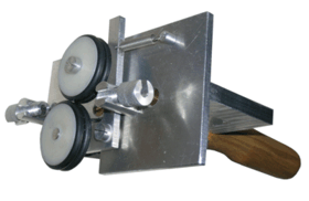
Fig.2 presents the photograph of a specialized Type 13 scanning device for
the wire inspection.

Fig.2. The Type 13 scanning device for the
wire inspection.
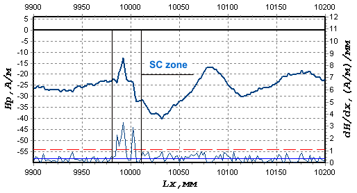
Fig.3 shows the fragment of the inspection results of a new ?2,6 mm (GOST
14959-79) wire.

Fig.3. The results of a new wire
inspection.
Inspection of steel ropes
The inspection of steel ropes is carried out using the Type 15 specialized
scanning device, which covers the rope along the entire perimeter. The high
effectiveness of the MMM method at inspection of both individual winds and the
entire rope section was revealed.
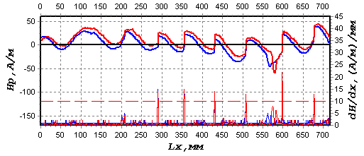
Fig.4 shows the results of the ?16 mm rope metal inspection after the
operating time of ~6700 load cycles on the mine equipment.

Fig.4. The results of the rope
inspection. |