Assessment of eguipment lifetime using the metal magnetic memory method
Dr., professor Anatoly Dubov
According to the "Standard guideline for metal inspection and
prolongation of TPS boilers, turbines and pipelines basic elements life", it is
suggested to consider crack resistance as the main parameter characterizing the
survivorship of power equipment units operating in conditions of cyclic loads.
However, this characteristic is determined on samples, and transferring of
laboratory testing results to real operational conditions does not provide an
objective assessment of metal condition.
The article considers the abilities of the method of metal magnetic
memory (MMM) to detect crack initiation zones directly on equipment and to trace
the development of metal fatigue failure process in these zones. Based on 100%
power equipment inspection using the MMM method it is suggested to detect all
potentially dangerous zones with developing defects and to timely remove them
during the repairs. Thus, an opportunity is offered to assess the real equipment
life.
Paper [1] presented in detail the problems of aging equipment’s residual life
assessment.
Among the basic scientific-technical problems of power equipment life
assessment the following should be singled out:
-
the lack of scientifically grounded concept of engineering diagnostics and
life estimation;
-
insufficient effectiveness of traditional non-destructive testing (NDT)
methods and means at early diagnostics of fatigue damages and investigation of
metal’s structural-mechanical properties;
-
low effectiveness of the current techniques for calibrating strength
calculation due to the lack of actual structural-mechanical properties of
metal by all equipment elements and units;
-
the lack in the broad practice of effective NDT methods and means allowing
performing 100% equipment inspection in order to assess the stress-strained
state and individual life of each unit and the entire aggregate.
The scientific-technical problems of equipment reliability assuring and
prolongation of its life are aggravated by the lack of the required financial
finds. According to estimation presented in the Concept of Technical
re-equipment of RSC "UES of Russia" Electric Power Plants till 2015, the
man-hours for providing of expert-predicted life, at its prolongation beyond the
body life, may be about 50% from the cost of complete replacement of similar
equipment’s power units. It is indicated that this high level of costs should be
aimed at a 100% diagnostic examination of equipment, execution of calibration
strength calculations and the analysis of technical-economic documentation on
the experience in equipment operation. It is obvious that these costs were
reasonable based on the experience in power equipment metal inspection gained by
RSC "UES of Russia" counting on a 100% examination by traditional destructive
and non-destructive testing methods.
Thus, nowadays at large Electric Power Plants, where equipment has exhausted
its body life, a deadlock condition has formed. There is no money for equipment
replacement and even for its 100% examination, and not a single organization
will obviously take a responsibility to prolong the life without such an
examination! At such conditions Power Plant management has to provide safe and
reliable operation of the equipment.
It should be noted that execution of a 100% examination of power equipment
using traditional NDT methods (UT, MPI, etc.) is associated not only with the
high level of costs, but also it has low effectiveness due to its unsuitability
for detection of fatigue damages at an early stage of their development.
According to standard guideline [2], it is suggested to consider crack
resistance as the main parameter characterizing the survivorship of power
equipment units operating in conditions of cyclic loads. It should be kept in
mind that this is a conventional material characteristic determined by the ratio
of the current (actual at a specific time and in specific conditions) crack
growth rate to the critical rate for a specific material. However, this
characteristic is determined on samples, and transferring of laboratory testing
results to real operational conditions does not provide an objective assessment
of equipment operability and efficiency.
Can assessment of cracks growth be made and their development zones be
detected in real conditions directly on equipment?
It is known that the main goal of a 100% examination is to detect potentially
dangerous stress concentration zones (SCZ), in which development of corrosion,
fatigue and creep damages occur. Exactly for solution of this problem it is
suggested to use the method of metal magnetic memory (MMM) the main designation
of which is SCZs detection based on express control of the entire equipment
surface. No preparatory works are required for this.
Most of power equipment units and elements operate in conditions of cyclic
loads, and after their long-term operation fatigue and/or creep damages should
be expected, which occur, as a rule, unexpectedly in local SCZs.
SCZs are not only the known beforehand areas, where structure peculiarities
create various conditions for distribution of stresses due to external operating
load, but also are randomly located areas, where large strains (shear strains,
as a rule) occurred due to metal inhomogeneity combined with off-design
additional working loads.
Paper [3] considers the physics of metal fatigue damaging and offers the
development model of this process opening the possibility of material’s state
quantitative assessment at using the MMM method.
It is established that fatigue damaging of metal has three phases:
-
the first stage is preparatory, it is characterized by comparatively high
rate and lasts for comparatively short period of 1,0-1,5% of the limiting
number of cycles;
-
the second phase - being the basic one - is an accumulative phase
characterized by very slow development of propagation process in one direction
- to the depth (from units to tens of microns) and lasting very long - for
90-95% of the limiting number of cycles;
-
the third phase - is the final one flowing very rapidly and causing
occurrence of microcracks in "random sites" and their propagation at a very
high speed to the depth and along the length and their growing into
macrocracks.
It should be noted that the first two phases of metal fatigue damaging
development in conditions of cyclic loading are well investigated, but the third
phase, which became a subject of numerous investigations, remains a secret to a
great extent.
Fig.1 shows graphic representation of the three phases of metal fatigue
damaging accumulation process in the form of dependence of metal weakened
(loosened) layer thickness δ on the number of load cycles N.
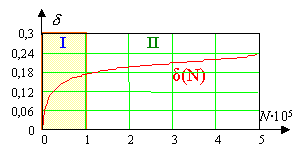
Fig.1а. |
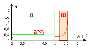
Fig.1b. |
Paper [3] gives quantitative representation of this diagram based on design
investigation for pipe sample in conditions of symmetric cyclic loading along
the radius.
Transience of the third phase and uncertainty of damaging initiation site did
not allow till date the detailed investigation of events preceding the failure
directly on equipment.
Let us further consider the abilities of the MMM method to trace the
development of metal fatigue failure process directly on equipment.
The main diagnostic parameter by the MMM method is the magnetic leakage field
gradient Нр (dНр/dx) or this field variation intensity
coefficient (Кin)1,
registered at scanning with a special magnetometer sensor along the equipment
surface. It was established that this very diagnostic parameter due to
magnetometric effect directly reflects the energy state of surface and depth
metal layers in SCZ [3]. And the maximum field gradient value, determined on the
metal surface with accuracy up to one millimeter, corresponds to the source of
crack occurrence. In the area of the most intensive strain and, finally, failure
process the domain structure suffers sufficient changes. Sizes of domains, whose
directions coincide with glide direction, reach critical sizes. As a result, the
maximum-size domain "breaks" and a microcrack appears. Design investigations in
paper [3] demonstrated that the domain of iron can have a volume covering up to
ten grains. At present Energodiagnostika Co. Ltd, due to its large experience in
power equipment examination, possesses quantitative values of Кin characterizing metal limiting state by
strength conditions and micro- and macrocracks2 development.
1 Kin=|ΔHp|/Δx
where |ΔHp| is the modular difference of the Нр magnetic field intensity between the adjacent measurement
points located at a distance Δx. At Δx->0, Кin=dHр/dx.
2 It should be noted that cracks division by micro and
macrocracks has till date a conventional nature in the technical literature.
Fig.2 shows inspection results of No.29 stage disk rim of No.3 unit K-300-240
turbine average-pressure rotor (APR) at Konakovo TPS (July, 2001). Нр field and its gradient dНр/dx distribution shown
in Fig.2, а characterizes the disk rim metal’s state. A "replica" for metal
structure investigation was taken in the Нр field and the maximum gradient value local
variation on the disk. Fig.2, b shows the photo illustrating the
results of metallographic investigation. Microcracks with 1 or 2 microns opening
can be seen.
Fig.2a. Results of disk rim
inspection. Distribution diagram of the Нр in SCZ.
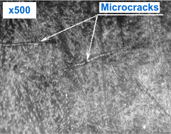
Fig.2b. Results of metallographic
investigation.
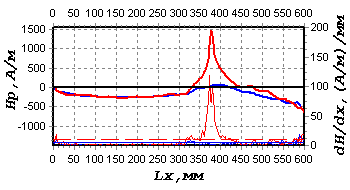
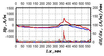
Fig.3, а shows the results of MMM-inspection along the output edge
of K-300-240 turbine LPR stage 38 blade No.12, unit No.5 at Konakovo TPS. A
"replica" for metal structure investigation was taken in the zone of abrupt
local variation of the Нр field
and its gradient. Fig.3, b shows the results of metallographic
investigation. A microcrack with 5-8 microns opening was revealed in the zone of
the field maximum gradient value dНр/dx.
This figure represents as well the results of the Нр field and its gradient measurements in the
microcrack zone before grinding (а), after primary grinding for taking
a replica (c) and after the secondary grinding (d). In this
case grinding on blade No.12 was perform to the depth of about 200 microns. The
dark stripe presented in Fig.3, b, corresponding to the crack location
on the blade surface, obviously represents the loosened metal layer. The dense
metal layer with increased hardness is under the loose layer. The results of
experimental investigation of similar blades, presented in paper [4], confirm
this.
 |
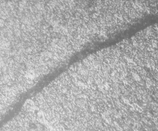 |
Fig.3a. |
Fig.3b. |
 |
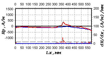 |
Fig.3c. |
Fig.3d. |
With the increase of the number of load cycles the dense metal layer cracks
increasing the size of the loose layer. Thus, a crack develops on the blade
surface. The results of experiment with blade No.12 grinding in the developing
crack region obviously demonstrate correlation of the diagnostic parameter dНр/dx with the damages
metal layer dimensions (depth and width). This correlation is also proved by the
physical "magnetodislocation" mechanism of the Нр magnetic field formation in the local SCZ
[3].
It should be noted that if the damaged metal layer is not removed in due
time, it may cause a serious blade or disk failure during the overhaul life. The
rate of a microcrack growing into a macrocrack is obviously different for each
specific unit. Such investigations are, as a rule, not carried out in real
conditional of critical equipment operation. Application of MMM at a 100%
examination of aging equipment will allow detecting crack formation zones and
assessing their propagation rate for various power equipment units in future. At
present there are some techniques for classification of the degree of metal
damaging in SCZs by the field gradient value.
It was established in the course of industrial investigations that the
diagnostic parameter values Кin in SCZs for the same-type
elements (for example, for blades of the same disk) during the same operation
time are, as a rule, different, for instance, due to the different amplitude of
cyclic load.
It is known that the damaging development rate in phases II and III for the
same-type elements is also, as a rule, different. This rate can be traced by the Кin value. This is the
basis of the methodology of life assessment by the Кin value presented in paper [5].
Paper [3] shows that decreasing of metal density in SCZs at accumulation of
fatigue damaging is accompanied by increasing of magnetic energy density and by
the diagnostic parameter Кin increasing respectively.
The gained experience in a 100% examination of K-300 turbines at Konakovo
TPS, К-200 at Cherepovetsk TPS and Zainsk TPS, Т-100 at Severodvinsk TPS-2,
PТ-60 and Т-100 at Petrozavodsk TPS and others (more than 50 various types of
turbines were examined in total) allows making the following conclusion: SCZs
are the sources of damages development (in the form of cracks, as a rule), which
occupy not more than 3-5% of the total rotors metal surface or volume. The
remaining 95% of the turbine rotors metal volume after their long-term operation
are in a satisfactory condition! Thus, the problem of turbine rotors life
assessment is solved by timely detection of maximum stress concentration zones
and their removal by ordinary grinding in the course of repairs. Similar
approach at life assessment with 100% examination by the MMM method is used by
Energodiagnostika Co. Ltd. on all types of power equipment: turbines, boilers,
steam and water pipelines, etc. And the costs for execution of such an
examination are sufficiently lower as compared to the cost of diagnostic works
indicated in the Concept of RSC "UES of Russia". For example, examination of all
three rotors of К-200 and К-300 turbines will make not more than 1 million
rubles (as of January, 2005).
References
1. Dubov А.А. Problems of aging equipment residual lifetime
assessment // Teploenergetika, No.11, 2003, p.54-58.
2. GD 10-577-03. Standard instruction for metal control and
prolongation of basic power station elements life. Moscow: SPO ORGRES, 2003.
3. Vlasov V.Т., Dubov А.А. Physical bases of the metal
magnetic memory method. Moscow: ZAO "TISSO", 2004. 424p.
4. Dubov А.А., Matunin V.М., Ryzhkov F.Е., Chechko I.I.
Early diagnostics of blades damaging using the method of metal magnetic memory
// Tyazheloye mashinistroyenie, No.10, 2001, p.32-34.
5. Dubov А.А., Dubov Al.An., Kolokolnikov S.М. Method of
metal magnetic memory and inspection devices. Training Handbook. Moscow: ZAO
"TISSO", 2008. 365p. |