Review of welding problems and allied processes and their solving using
metal magnetic memory effect
Dr., Professor A.A. Dubov, S.M. Kolokolnikov
The welding exists in the world more than 100 years, however the many
problems of a quality control of products welded joints and reliability control
of welded constructions, till now take place. Among the most important problems
are:
-
Low effectiveness of traditional means and methods at stress-strained state
control of welded joints and determination of stress concentration zones - the
sources of damages development.
-
Lack in the general practice of norms on defect size tolerances from the
position of fracture mechanics.
-
Structure buckling or its shape and dimensions variation due to
inhomogeneous heating and cooling at welding.
-
Lack of effective non-destructive (NDT) methods of quality control of
thermal and other welded joints treatment technologies for residual stresses
relief.
-
Lack of effective methods of contact welding NDT in products of mechanical
engineering; till date in practice detachment testing is conducted by impact
at the spot welding location with hammer and chisel.
-
Selection of optimum welding technologies, deposits, spraying, is a problem
task.
-
Low effectiveness of traditional NDT methods at control of contact welding
of pipes, fillet and welded T-joints.
One of the important and complex problems of a modern non-destructive testing
(NDT) of quality of different types weld joints is the searching and definition
in them of "a weak link" in a uniform overall system of the factors
"structural-mechanical heterogeneity - flaws of a weld - constructive and
technological stress concentrator", i.e. zones with high heterogeneity of the
stress-strained state or zones of stress concentration (SCZ). It is important
for optimisation of technological procedure both at manufacture of welded
joints, i.e. immediately after welding, and at their exploitation.
Traditional non-destructive testing, oriented only at detection of
discontinuity flaws in welded joints, cannot provide authentic assessment of
their quality. It is difficult for a welding technologist to reveal the reasons
of weld unsoundness and improve welding technology based only on NDT
results.
In conditions when many factors influence reliability of welded joints, it is
necessary NDT method for integral estimate of welded joint metal state.
Now in Russia a principally new method for diagnostics of products metal and
welded joints with usage of metal magnetic memory (MMM) is developed at a level
of the national standard and successfully applied in various industries.
The MMM method is oriented to solution of the above indicated problems of
base metal and welded joints NDT on industrial and transport objects.
Method of metal magnetic memory is non-destructive testing method based on
the analysis of distribution of self-magnetic leakage field (SMLF) on
components’ surfaces for determination of stress concentration zones (SCZ),
imperfections and heterogeneity of metal structures and welded joints.
By reading SMLF, reflected residual magnetization, which is formed during
welding, the unique opportunity is given us to execute an estimation of an
actual state of a weld. And this estimation is integral and represents in each
weld simultaneously features of a structural state, distribution of residual
stresses and defects of welding.
The forming of magnetic (domain) structure in welded joints occurs
simultaneously with crystallization at metal cooling in the magnetic field of
the Earth while transiting through a Curie point (768oС) under action of
stresses and strains arisen from welding. On arising imperfections of welding
the points of domains attachment are formed with an exit on a surface of a weld
as self-magnetic leakage fields. Thus, by reading SMLF, which are formed during
welding, the opportunity is given us to execute an integral estimation of an
actual state of a weld.
The inspection is carrying out by MMM method without dressing of metal and
special magnetization. MMM method allows to carry out express quality control of
welded joints in a manual both automatic mode at mass production of various
products from carbonaceous, austenitic and ferrite-austenitic steel grade.
The inspection is carrying out with usage of the specialized small-sized
devices with self-contained power supply, scanning and recording devices. The
magnetometric testers of stress concentration (TSC) have no analogues. The
devices are manufactured by Energodiagnostika Co. Ltd (Moscow, Russia), are
certificated in Gosstandart of the Russian Federation and included in the state
register of measuring instruments.
The inspection scheme of butt welded joint is shown on the figure 1. As it is
visible from the figure 1, at inspection the ferro-probe converters 1 and 3 is arranged in heat-affected zones (HAZ) from both sides of a
weld, the converter 2 is arranged between them in the middle, and the
converter 4 is arranged vertically in the opposite direction and
intended for tuning out of an external magnetic field.
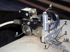
Fig.1. The scheme of monitoring of butt
welded joints of tubes by the four-channels sensor of the device TSC-1M-4: 1, 2,
3 - the ferro-probe converters of the scanner for registration of Нр field on a surface of a weld; 4 - the ferro-probe
converter for tuning out of an external magnetic field Нр;
5 - driving wheels of the meter of length; ΔLb - base
distance between ferro-probe converters.
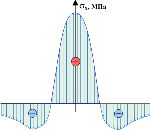
Fig.2, а shows typical distribution of residual stresses on a welded
joint of plates. Fig.2, b shows distribution of the tangential
component of the magnetic leakage field Нрx registered at
MMM inspection at measurement of the field perpendicular to the weld. These
figures show a good qualitative convergence of residual stresses and the
magnetic field distributions.
 |
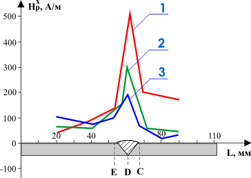 |
Fig.2a. Typical distribution
of residual stresses on a welded joint of plates. |
Fig.2b. Distribution of the
tangential component of the field Hpx at measurement of the field
perpendicular to the weld: 1, 2, 3 - different sections of the
plate. |
It is known that the on-line inspection of welded joints heat treatment
quality is conducted, as a rule, only by measuring of metal hardness. However,
such spot inspection does not ensure the absence of mechanical stresses
concentrators across the entire weld and in the regions adjacent to it.
Let us further consider the MMM method effectiveness at quality control of
the weld heat treatment on a ?220х20 mm pipe length of the 12Cr1MoV type
low-alloyed steel grade. Heat treatment was conducted with weld metal heating
from the induction coil up to 700oС with subsequent cooling in air.
Fig.3 presents magnetograms characterizing the pipe length’s stress-strained
state far from the weld (3, а) and the weld metal respectively before
(3, b) and after the heat treatment (3, c). The magnetograms
were obtained as a result of MLPC measurements along the pipe and the weld
perimeter according the scheme presented in Fig.1. From comparison of Fig.3, b and 3, c it is seen that the magnetogram registered on the
weld after the heat treatment turned out to be similar to that registered in the
initial state on the pipe surface far from the weld. The experiment shown in
Fig.3 suggests a conclusion that a magnetogram measured along the pipe perimeter
near the welded joint, where there is no influence of welding, can be taken as a
standard reference sample.
Fig.3. Magnetograms characterizing the pipe
length’s stress-strained state far from the weld (a) and the weld metal
respectively before heat treatment (b) and after heat treatment
(c).
Fig.4 shows measurement results of the Нр field normal
component characterizing distribution of residual stresses and strains after
welding of two identical plates. During welding plates were loose and bent
slightly upwards. The Нр field distribution in the
considered case shows visually the influence of plates geometrical dimensions
and their buckling on residual strains and stresses distribution level and
pattern.
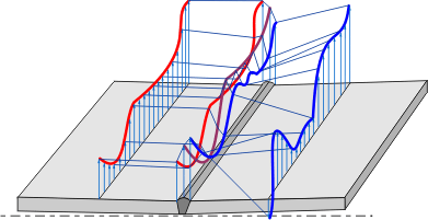
Fig.4.
Fig.5, a shows the Нр field distribution on the
pipe welded joint registered in heat affected zones (HAZ), and Fig.5, b shows distribution of residual stresses measured on the weld by an X-ray
diffractometer in the same zones.
The welded joint quality according to the MMM method is assessed by the
distribution pattern of the magnetic field Нр and its
gradient dНр/dx where dx is the minimum
distance between two adjacent measurement points of the Нр field. The gradient value is
determined automatically as a modular difference |ΔНр|
divided by the discrete distance Δх between the two adjacent
measurement points, set at preliminary adjustment of the instrument.
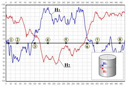
Fig.5a. Stressed-strained state of
the pipe welded joint (?160x8mm, steel 3) according to inspection results by the
metal magnetic memory method: Н1 и Н2 - field distribution on first
and second measurement channel.
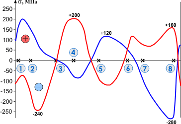
Fig.5b. Stressed-strained state of
the pipe welded joint (?160x8mm, steel 3) according to inspection results by an
X-ray diffractometer: 1...8 - points of stress measurement by an X-ray
diffractometer symmetrically from two sides of the weld in HAZ; --- results of stress measurement
corresponding to Н1; --- results of stress measurement
corresponding to Н2.
In the Fig.6, a the distribution of the normal component of a field Нр lengthways of the inspected
weld segment of the lower floor of the polymerization reactor at the enterprise
"Anwil" S.A. (Vlotslavek, Poland) is shown. In the Fig.6, b the
disposition of detected cracks is marked. In zones of the detected cracks the
polar distribution of a magnetic field on channels Н1 and Н2 is recorded. The segment of a SC line
(Нр=0) (see Fig.6, б)
with the maximal gradient dНр/dx is situated in HAZ of the weld and
is the prolongation of the detected crack.
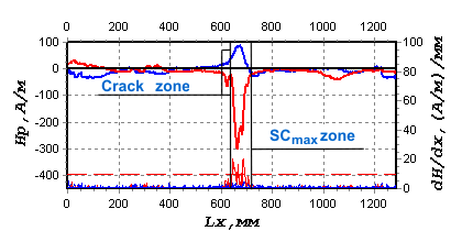
Fig.6a. The distribution of the
normal component of a field Нр lengthways of the inspected
weld segment.
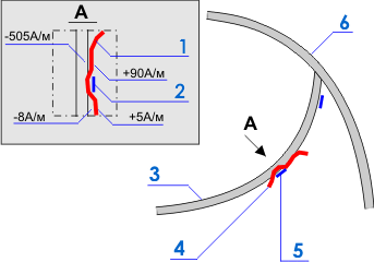
Fig.6b. The disposition of detected
cracks: 1, 4 - SC line (Hp=0); 2, 5 - crack; 3 - radial
weld; 6 - girth weld.
As a result of inspection the following outputs and recommendations were
made:
-
The crack is an developing imperfection in the direction of the maximal
SCZ.
-
Removing of metal and welding should be carried out not only in area of
detected crack, but also in area of maximal stress concentration for
prevention of a crack development while in service.
It is known that the residual strain of the weld metal is formed due to shear
plastic strain occurring at crystallization in the course of metal cooling.
Diagnostic parameters Нр and its gradien Кin (dНр/dx) owing to
"magnetic-dislocation" hysteresis due to duality of the magnetic plane and the
glade plane of dislocations, reflect distribution of residual strains and
stresses along the welded joint perimeter.
The ratio between limiting values of magnetic parameters mlim , Кint, Кinyand mechanical
characteristics of metal σt and σy is
given in the paper [1]:
mlim = Кint / Кiny ≈
(σt / σy)2,
(1)
where mlim - is
magnetic index of limiting strain hardening; Кint and Кiny - are gradients of a
field obtained at tensile test of samples at attainment of the yield strength
σy and the tensile strength σt accordingly.
It should be noted that the ratio (1), obtained in the course of experimental
investigations, was confirmed by the design investigations presented in the
paper [2], and it is conditioned by the squared relationship of the parameter Кin to the magnetic
and, accordingly, the mechanical energy accumulated in the metal of a SCZ.
The method of the field gradient Кint and Кiny determination in
industrial conditions is stated in paper [1]. As a rule, the maximum value Кinmax revealed in certain HAZ, corresponds to Кint and the average value Кinave calculated for all HAZs revealed at equipment inspection, is conventionally
equated to the value of Кiny.
Then the ratio (1) can be expressed as follows:
mlim = Кinmax / Кinave ≈
(σmax / σave)2, (2)
where σmax and
σave - are accordingly
maximal value of stress in SCZ and average value of stress for all SCZs detected
at the inspection.
Ratios (1) and (2) were obtained in the course of laboratory and industrial
investigations for the base metal. These ratios can be applied to welded joints,
except for local stress concentration zones due to welding defects (pores, slag
inclusions, poor penetration, etc.).
According to [3], the stress concentration coefficient for a welded joint is
equal to:
Кd ≈ σmax / σave, (3)
where σmax - are
maximum stresses in HAZ; σave - is an average stress in a welded
joint.
Paper [3] gives evaluation of Кd:
It is obvious that ratios (1) and (2) can be also used for local HAZs due to
welding defects with correction for defect dimensions and depth of their
bedding.
Here it is important to point out the delusiveness in the existing approaches
of various inspection means developers at assessment of residual stress
distribution in welded joints. As a rule, according to the results of the
inspection by various methods (strain measurement and interferometry with metal
drilling, X-ray, UT, Barkhausen effect, the magnetic anisotropy method, etc.),
the level of residual stresses on welds does not exceed the yield strength
σy, which, as a rule, does not correspond to the actual
distribution of stresses.
As the practice shows, the level of the directed residual stresses (normal or
tangential) in a SCZ may meet 1000 MPa and greater. This stress level may have
much greater values in the zones of the developing welding defects and cracks.
These practical observations clearly confirm the results of welded joints
inspection by the MMM method in a SCZ and outside it combination, for example,
with hardness measurement and conversion of its results to stress units. For
example, the level of "contact" stresses measured with hardness gages at MEI in
SCZs, detected by eth MMM method, often met 1500 MPa and greater. One should
keep in mind that strains and stresses are volumetric and have at least three
components (radial and two tangential) in each inspection point.
Distribution of SMLF in each inspection "point", measured with
three-component sensors with the accuracy up to 1 mm on the weld metal surface
and in HAZ, according to the available technique, directly reflects the triaxial
distribution of residual stresses and strains. At that it isn’t important to
know the level of absolute stresses (though this problem is solved in the MMM
method!), but their distribution to the depth and along the surface. And the
most important thing is, at the same time, not to allow the limiting state of
the metal before the crack formation.
Now in Russia the method of metal magnetic memory has obtained wide
development:
-
About 40 guiding documents and techniques for inspection of equipment in
different industries are developed.
-
The standard of the Russian Welding Society ST RWS 004-03 "Non-destructive
testing. Welded joints of equipment and constructions. Method of metal
magnetic memory (MMM-inspection)" is approved.
-
Two standards of Russia are approved: GOST R 52005-2003 "Non-destructive
testing. Method of metal magnetic memory. General requirements" and GOST R
52081-2003 "Non-destructive testing. Method of metal magnetic memory. The
terms and definitions".
The International Standard ISO 24497-1, 24497-2, 24497-3 on the metal
magnetic memory method is approved in 2007 as a result of positive voting among
18 IIW member countries and more than 10 ISO Committee countries.
Reference
1. Dubov A.A., Dubov Al.A., Kolokolnikov S.M. Method of
metal magnetic memory and inspection devices. Training handbook. Moscow: ZAO
"TISSO", 2008. 365p.
2. Vlasov V.T., Dubov A.A. Basis physics of the metal
magnetic memory method. Moscow: ZAO "TISSO", 2004. 424p.
3. Fedorov S.A. Quality control of welded and soldered
joints. Training handbook. Moscow: MATI, 1989. 201p. |